


The function of the liquid crystal display power supply circuit is mainly to convert the 220V mains power into various stable direct currents required for the operation of the liquid crystal display, and to provide working voltage for various control circuits, logic circuits, control panels, etc. in the liquid crystal display, and its working stability It directly affects whether the LCD monitor can work normally.
1. The structure of the liquid crystal display power supply circuit
The liquid crystal display power supply circuit mainly generates 5V, 12V working voltage. Among them, the 5V voltage mainly provides working voltage for the logic circuit of the main board and the indicator lights on the operation panel; the 12V voltage mainly provides the working voltage for the high-voltage board and the driver board.
The power circuit is mainly composed of filter circuit, bridge rectifier filter circuit, main switch circuit, switching transformer, rectifier filter circuit, protection circuit, soft start circuit, PWM controller and so on.
Among them, the role of the AC filter circuit is to eliminate high-frequency interference in the mains (linear filter circuit is generally composed of resistors, capacitors and inductors); the role of the bridge rectifier filter circuit is to convert 220V AC into 310V DC; switch circuit The function of the rectification filter circuit is to convert the DC power of about 310V through the switching tube and the switching transformer into pulse voltages of different amplitudes; the function of the rectification filter circuit is to convert the pulse voltage output by the switching transformer into the basic voltage 5V required by the load after rectification and filtering and 12V; The function of the overvoltage protection circuit is to avoid the damage of the switching tube or the switching power supply caused by abnormal load or other reasons; the function of the PWM controller is to control the switching of the switching tube and control the circuit according to the feedback voltage of the protection circuit.
Second, the working principle of the liquid crystal display power supply circuit
The power supply circuit of the liquid crystal display generally adopts the switching circuit mode. This power supply circuit converts the AC 220V input voltage into a DC voltage through a rectification and filtering circuit, and then is cut by a switching tube and stepped down by a high-frequency transformer to obtain a high-frequency rectangular wave voltage. After rectification and filtering, the DC voltage required by each module of the LCD is output.
The following takes the AOCLM729 liquid crystal display as an example to explain the working principle of the liquid crystal display power supply circuit. The power circuit of AOCLM729 liquid crystal display is mainly composed of AC filter circuit, bridge rectifier circuit, soft start circuit, main switch circuit, rectifier filter circuit, overvoltage protection circuit and so on.
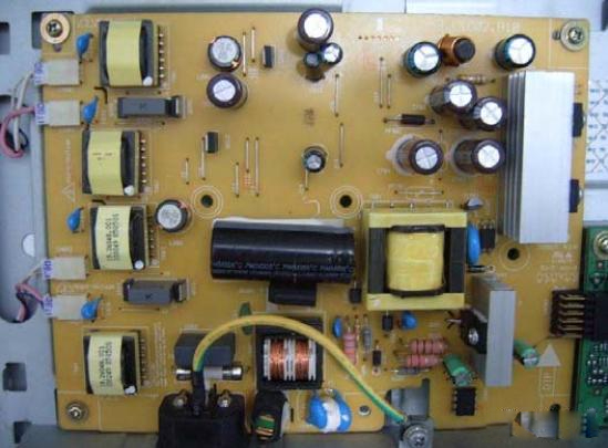
The physical picture of the power circuit board:
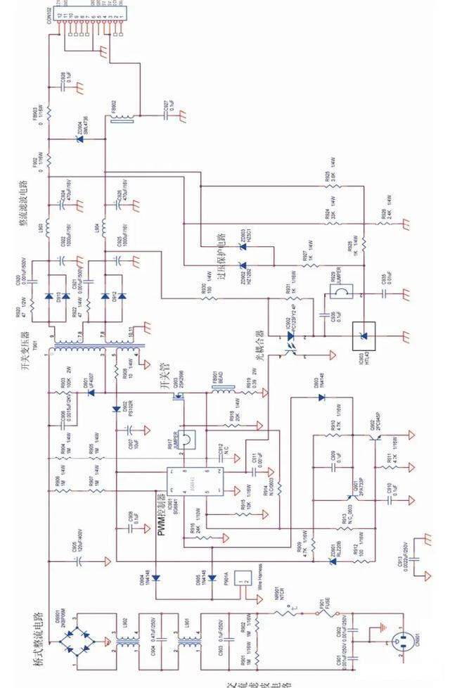
Schematic diagram of the power circuit:
- AC filter circuit
The function of the AC filter circuit is to filter out the noise introduced by the AC input line and suppress the feedback noise generated inside the power supply.
The noise inside the power supply mainly includes common mode noise and normal noise. For single-phase power supply, there are 2 AC power wires and 1 ground wire on the input side. The noise generated between the two AC power lines and the ground wire on the power input side is common noise; the noise generated between the two AC power lines is normal noise. The AC filter circuit is mainly used to filter out these two types of noise. In addition, it also serves as circuit overcurrent protection and overvoltage protection. Among them, the fuse is used for overcurrent protection, and the varistor is used for input voltage overvoltage protection. The figure below is the schematic diagram of the AC filter circuit.
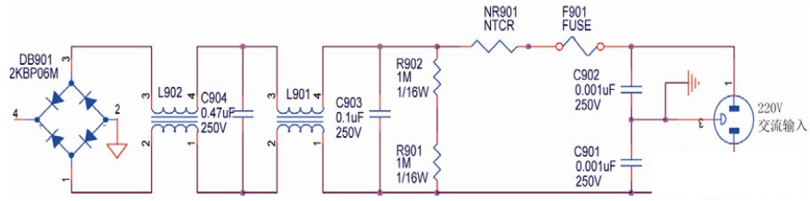
In the figure, inductors L901, L902, and capacitors C904, C903, C902, and C901 form an EMI filter. Inductors L901 and L902 are used to filter low frequency common noise; C901 and C902 are used to filter low frequency normal noise; C903 and C904 are used to filter high frequency common noise and normal noise (high frequency electromagnetic interference); current limiting resistor R901 and R902 are used to discharge the capacitor when the power plug is unplugged; insurance F901 is used for overcurrent protection, and varistor NR901 is used for input voltage overvoltage protection.
When the power plug of the liquid crystal display is inserted into the power socket, the 220V AC passes through the fuse F901 and the varistor NR901 to prevent surge impact, and then passes through the circuit composed of capacitors C901, C902, C903, C904, resistors R901, R902, and inductors L901, L902. Enter the bridge rectifier circuit after the anti-interference circuit.
2. Bridge rectifier filter circuit
The function of the bridge rectifier filter circuit is to convert the 220V AC into a DC voltage after full-wave rectification, and then convert the voltage into twice the mains voltage after filtering.
The bridge rectifier filter circuit is mainly composed of bridge rectifier DB901 and filter capacitor C905.
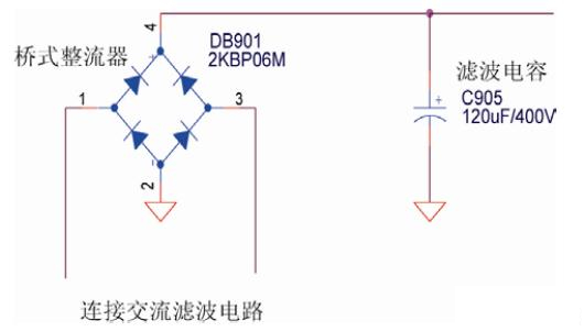
In the figure, the bridge rectifier is composed of 4 rectifier diodes, and the filter capacitor is a 400V capacitor. When the 220V AC mains is filtered, it enters the bridge rectifier. After the bridge rectifier performs full-wave rectification on the AC mains, it becomes a DC voltage. Then the DC voltage is converted into a 310V DC voltage through the filter capacitor C905.
3. soft start circuit
The function of the soft start circuit is to prevent the instantaneous impact current on the capacitor to ensure the normal and reliable operation of the switching power supply. Since the initial voltage on the capacitor is zero at the moment when the input circuit is powered on, a large instantaneous inrush current will be formed, and this current will often cause the input fuse to blow out, so a soft-start circuit needs to be set. The soft start circuit is mainly composed of starting resistors, rectifier diodes, and filter capacitors. As shown in the figure is the schematic diagram of the soft start circuit.
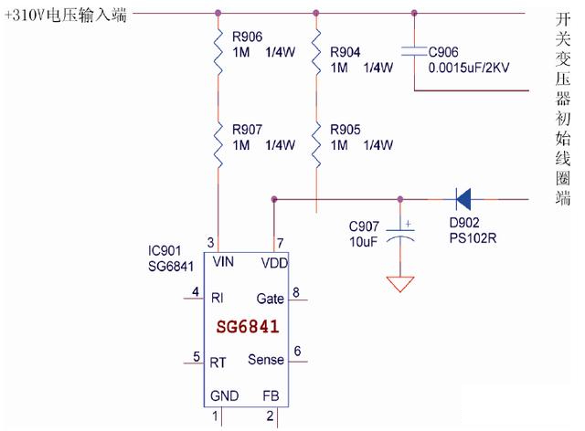
In the figure, the resistors R906 and R907 are equivalent resistors of 1MΩ. Since these resistors have a large resistance value, their working current is very small. When the switching power supply is just started, the starting working current required by the SG6841 is added to the input terminal (pin 3) of the SG6841 after being stepped down by the 300V DC high voltage through the resistors R906 and R907 to realize soft start. Once the switching tube turns into normal working state, the high-frequency voltage established on the switching transformer is rectified and filtered by the rectifier diode D902 and the filter capacitor C907, and then becomes the working voltage of the SG6841 chip, and the start-up process is over.
4. main switch circuit
The function of the main switch circuit is to obtain a high-frequency rectangular wave voltage through switching tube chopping and high-frequency transformer step-down.
The main switching circuit is mainly composed of switching tube, PWM controller, switching transformer, overcurrent protection circuit, high voltage protection circuit and so on.
In the figure, SG6841 is a PWM controller, which is the core of the switching power supply. It can generate a driving signal with a fixed frequency and an adjustable pulse width, and control the on-off state of the switching tube, thereby adjusting the output voltage to achieve the purpose of voltage stabilization. . Q903 is a switching tube, T901 is a switching transformer, and the circuit composed of voltage regulator tube ZD901, resistor R911, transistors Q902 and Q901, and resistor R901 is an overvoltage protection circuit.
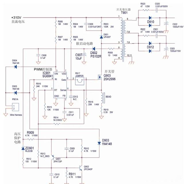
When the PWM starts to work, the 8th pin of SG6841 outputs a rectangular pulse wave (generally the frequency of the output pulse is 58.5kHz, and the duty cycle is 11.4%). The pulse controls the switching tube Q903 to perform switching action according to its operating frequency. When the switching tube Q903 is continuously turned on/off to form self-excited oscillation, the transformer T901 starts to work and generates an oscillating voltage.
When the output terminal of pin 8 of SG6841 is high level, the switching tube Q903 is turned on, and then the primary coil of the switching transformer T901 has a current flowing through it, which generates positive and negative voltages; at the same time, the secondary of the transformer generates positive and negative voltages. At this time, the diode D910 on the secondary is cut off, and this stage is the energy storage stage; when the output terminal of pin 8 of SG6841 is at low level, the switch tube Q903 is cut off, and the current on the primary coil of the switching transformer T901 changes instantaneously. is 0, the electromotive force of the primary is lower positive and upper negative, and the electromotive force of upper positive and lower negative is induced on the secondary. At this time, the diode D910 is turned on and starts to output voltage.
(1) Overcurrent protection circuit
The working principle of the overcurrent protection circuit is as follows.
After the switch tube Q903 is turned on, the current will flow from the drain to the source of the switch tube Q903, and a voltage will be generated on R917. Resistor R917 is a current detection resistor, and the voltage generated by it is directly added to the non-inverting input terminal of the overcurrent detection comparator of the PWM controller SG6841 chip (namely pin 6), as long as the voltage exceeds 1V, it will make the PWM controller SG6841 internal The current protection circuit starts, so that the 8th pin stops outputting pulse waves, and the switching tube and switching transformer stop working to realize over-current protection.
(2) High voltage protection circuit
The working principle of the high voltage protection circuit is as follows.
When the grid voltage increases beyond the maximum value, the output voltage of the transformer feedback coil will also increase. The voltage will exceed 20V, at this time the voltage regulator tube ZD901 is broken down, and a voltage drop occurs on the resistor R911. When the voltage drop is 0.6V, the transistor Q902 is turned on, and then the base of the transistor Q901 becomes high level, so that the transistor Q901 is also turned on. At the same time, the diode D903 is also turned on, causing the 4th pin of the PWM controller SG6841 chip to be grounded, resulting in an instantaneous short-circuit current, which makes the PWM controller SG6841 quickly turn off the pulse output.
In addition, after the transistor Q902 is turned on, the 15V reference voltage of pin 7 of the PWM controller SG6841 is directly grounded through the resistor R909 and the transistor Q901. In this way, the voltage of the power supply terminal of the PWM controller SG6841 chip becomes 0, the PWM controller stops outputting pulse waves, and the switching tube and switching transformer stop working to achieve high-voltage protection.
5. Rectifier filter circuit
The function of the rectification filter circuit is to rectify and filter the output voltage of the transformer to obtain a stable DC voltage. Because of the leakage inductance of the switching transformer and the spike caused by the reverse recovery current of the output diode, both form a potential electromagnetic interference. Therefore, to obtain pure 5V and 12V voltages, the output voltage of the switching transformer must be rectified and filtered.
The rectifier filter circuit is mainly composed of diodes, filter resistors, filter capacitors, filter inductors, etc.
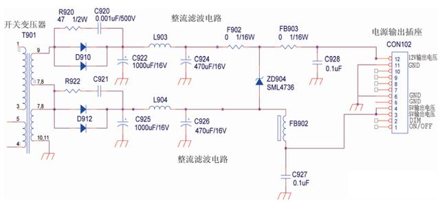
In the figure, the RC filter circuit (resistor R920 and capacitor C920, resistor R922 and capacitor C921) connected in parallel to the diode D910 and D912 at the secondary output end of the switching transformer T901 is used to absorb the surge voltage generated on the diode D910 and D912.
The LC filter composed of diode D910, capacitor C920, resistor R920, inductor L903, capacitors C922 and C924 can filter the electromagnetic interference of the 12V voltage output by the transformer and output a stable 12V voltage.
The LC filter composed of diode D912, capacitor C921, resistor R921, inductor L904, capacitors C923 and C925 can filter the electromagnetic interference of the 5V output voltage of the transformer and output a stable 5V voltage.
6. 12V/5V regulator control circuit
Since the 220V AC mains power changes within a certain range, when the mains power rises, the output voltage of the transformer in the power circuit will also rise accordingly. In order to obtain stable 5V and 12V voltages, a Regulator circuit.
The 12V/5V voltage regulator circuit is mainly composed of a precision voltage regulator (TL431), an optocoupler, a PWM controller, and a voltage divider resistor.
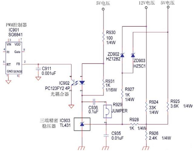
In the figure, IC902 is an optocoupler, IC903 is a precision voltage regulator, and resistors R924 and R926 are voltage divider resistors.
When the power supply circuit is working, the 12V output DC voltage is divided by the resistors R924 and R926, and a voltage is generated on R926, which is directly added to the TL431 precision voltage regulator (to the R terminal). It can be known from the resistance parameters on the circuit This voltage is just enough to turn on the TL431. In this way, the 5V voltage can flow through the optocoupler and the precision voltage regulator. When the current flows through the optocoupler LED, the optocoupler IC902 starts to work and completes the voltage sampling.
When the 220V AC mains voltage rises and the output voltage rises accordingly, the current flowing through the optocoupler IC902 will also increase accordingly, and the brightness of the light-emitting diode inside the optocoupler will also increase accordingly. The internal resistance of the phototransistor also becomes smaller at the same time, so that the conduction degree of the phototransistor terminal will also be strengthened. When the conduction degree of the phototransistor is strengthened, the voltage of the pin 2 of the PWM power controller SG6841 chip will drop at the same time. Since this voltage is added to the inverting input of the internal error amplifier of SG6841, the duty cycle of the output pulse of SG6841 is controlled to reduce the output voltage. In this way, the overvoltage output feedback loop is formed to achieve the function of stabilizing the output, and the output voltage can be stabilized at around 12V and 5V output.
hint:
An optocoupler uses light as a medium to transmit electrical signals. It has a good isolation effect on input and output electrical signals, so it is widely used in various circuits. At present, it has become one of the most diverse and widely used optoelectronic devices. An optocoupler generally consists of three parts: light emission, light reception, and signal amplification. The input electrical signal drives the light-emitting diode (LED) to emit light of a certain wavelength, which is received by the photodetector to generate a photocurrent, which is further amplified and output. This completes the electrical-optical-electrical conversion, thus playing the role of input, output, and isolation. Since the input and output of the optocoupler are isolated from each other, and the electrical signal transmission has the characteristics of unidirectionality, it has good electrical insulation ability and anti-interference ability. And because the input end of the optocoupler is a low-impedance element that operates in the current mode, it has a strong common-mode rejection capability. Therefore, it can greatly improve the signal-to-noise ratio as a terminal isolation element in long-term transmission of information. As an interface device for signal isolation in computer digital communication and real-time control, it can greatly increase the reliability of computer work.
7. overvoltage protection circuit
The function of the overvoltage protection circuit is to detect the output voltage of the output circuit. When the output voltage of the transformer rises abnormally, the pulse output is turned off by the PWM controller to achieve the purpose of protecting the circuit.
The overvoltage protection circuit is mainly composed of a PWM controller, an optocoupler, and a voltage regulator tube. As shown in the above figure, the voltage regulator tube ZD902 or ZD903 in the circuit schematic diagram is used to detect the output voltage.
When the secondary output voltage of the switching transformer rises abnormally, the voltage regulator tube ZD902 or ZD903 will be broken down, which will cause the brightness of the light-emitting tube inside the optocoupler to increase abnormally, causing the second pin of the PWM controller to pass through the optocoupler. The phototransistor inside the device is grounded, the PWM controller quickly cuts off the pulse output of pin 8, and the switching tube and switching transformer stop working immediately to achieve the purpose of protecting the circuit.
Post time: Oct-07-2023